1
/
of
1
NovaPro UHD
NovaPro UHD
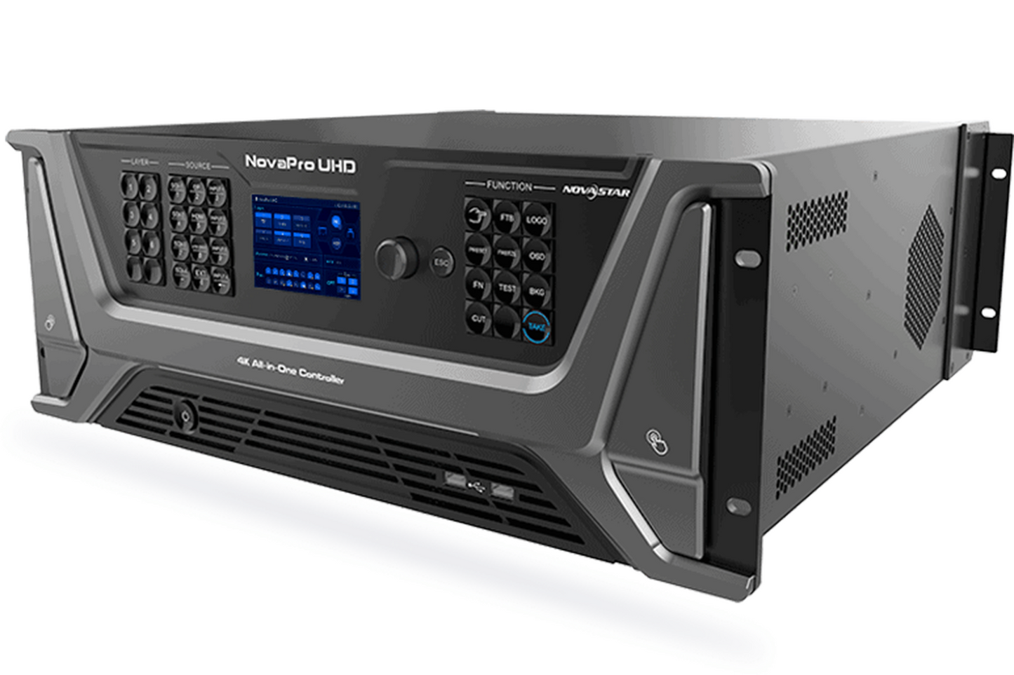
NovaPro UHD is an all-in-one controller, integrating a software control system with 4K processing and 4K sending. The NovaPro UHD features many cutting edge technologies, and a single unit is able to provide comprehensive control for high end rental and other applications, simplifying operation while increasing the value of the display.
Specifications
Input
| Connector | Quantity | Description |
| 12G-SDI | 4 | Supports ST-2082-1 (12G), ST-2081-1 (6G), ST-424 (3G) and ST-292 (HD) standard video inputs. Input resolutions up to 4K×2K@60Hz and downward compatible Supports 12G-SDI output with loop-through.Note:When the input source is a 12G-SDI signal, you must use CANARE / L-4.5CHD+ / UHDTV-SDI SDI cables and the cable length should be less than 50 m.12G-SDI connectors 1, 2 and 3 DO NOT support the deinterlaced function, but connector 4 supports the function. |
| DP 1.2 | 1 |
|
| HDMI 2.0 | 1 |
|
| HDMI 1.3 | 4 |
|
Output
| Connector | Quantity | Description |
| Ethernet port | 16 | Gigabit Ethernet output ports
|
| OPT 1–4 | 4 | 10G fiber optical output ports (copy and hot backup)
|
| MVR | 1 | HDMI 1.3 connector A Multiviewer connector to monitor the input source, PVM, PGM or perform mixed monitoring |
| AUX | 1 | HDMI 1.3 connectorAn auxiliary output connector for connecting an auxiliary device, such as a teleprompter |
Control
| Connector | Quantity | Description |
| ETHERNET | 1 | For PC communication or network connection |
| USB | 3 |
|
| GENLOCK IN-LOOP | 1 | Connect a synchronization signal source to synchronize the cascaded devices. |
| CONTROL UI | 1 | Connect to a monitor for displaying the user interface of the embedded Master VI software. |
For more information, please visit the manufacturer's website